Understanding the distinction between mesh and CAD files is crucial for anyone working in 3D design, manufacturing, or digital modeling. While both file types represent three-dimensional objects, they serve different purposes and offer unique advantages depending on your specific application.
Because of this, choosing the right file format can significantly impact your workflow efficiency and final results. To help you pick the right one for your business, let’s take the time to explore the fundamental differences between mesh and CAD files.
What is a Mesh File?
A mesh file represents 3D objects through interconnected geometric elements forming the surface of a model. It consists of three main components: vertices, edges, and faces. Think of it as a digital wireframe defining the external shape of an object with thousands of small triangles or polygons.
Mesh files are simple and versatile. Common formats include STL (Standard Tessellation Language), OBJ (Wavefront OBJ), PLY (Polygon File Format), and 3MF (3D Manufacturing Format). Each has its strengths—STL is ideal for 3D printing, while OBJ supports texture mapping for visual applications.
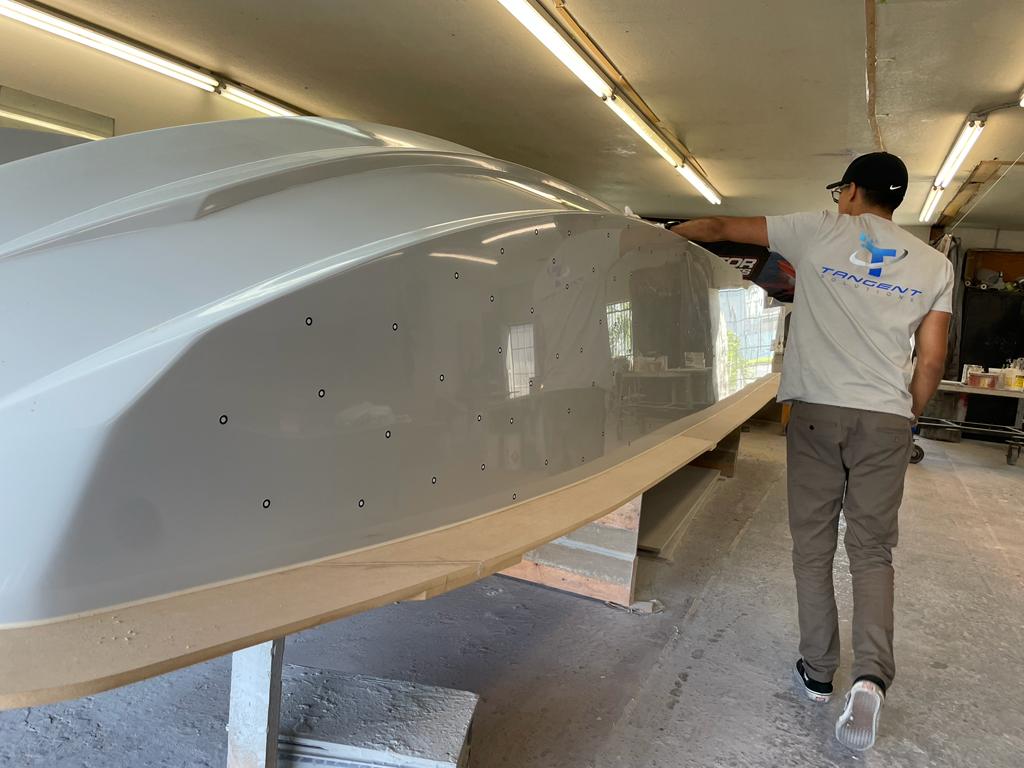
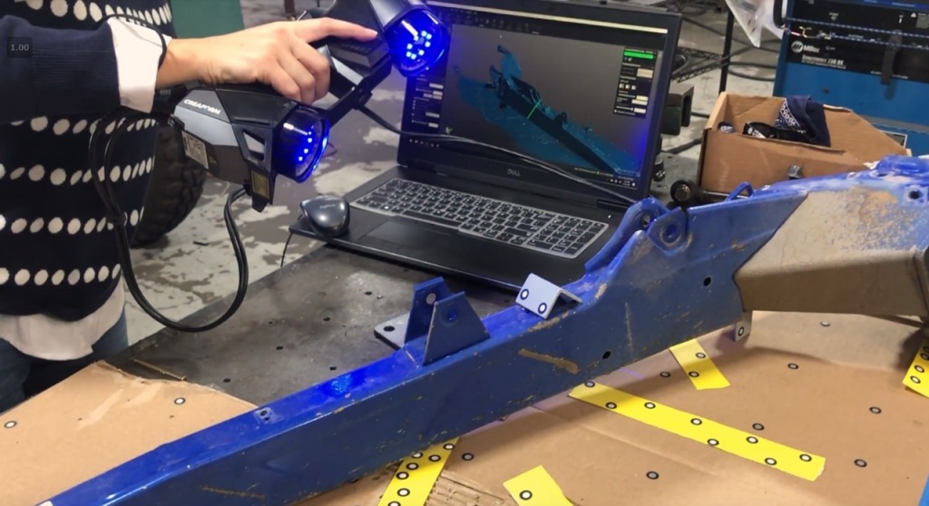
Many industries regularly use mesh files. In 3D printing, STL is the standard for communicating surface geometry to slicing software. Gaming and animation rely on mesh files for character models and environments, while 3D scanning outputs mesh files for reverse engineering and quality inspection work.
What is a CAD File?

CAD (Computer-Aided Design) files use a different approach to representing 3D objects. Instead of surface approximations, CAD files rely on parametric, feature-based modeling that captures the design intent, including dimensions, constraints, and relationships between elements.
CAD files use features like extrusions, cuts, fillets, and patterns that combine to create complex geometries. Common formats include STEP (Standard for Exchange of Product Data), IGES (Initial Graphics Exchange Specification), DWG (AutoCAD Drawing), and native formats like SLDPRT (SolidWorks) or F3D (Fusion 360).
CAD files are essential in engineering and manufacturing, where precision, editability, and documentation are key. Engineers use CAD to create products with exact tolerances, while manufacturers rely on it to program CNC machines, develop tooling, and generate technical drawings. Industries like automotive, aerospace, and medical devices depend on CAD for maintaining design integrity in complex projects.
Key Differences Between Mesh and CAD Files
While some of the differences between mesh and CAD files might seem obvious now that you know what they are, it’s essential to understand the finer details that set them apart. Here are the key elements to focus on.
Data Representation
The most fundamental difference lies in how each file type represents geometric information. Mesh files use discrete approximations—they break curved surfaces into small flat facets, similar to how pixels approximate smooth curves on your computer screen. CAD files maintain mathematical precision by storing exact geometric definitions using curves, surfaces, and solid models.
Editing Capabilities
CAD files offer superior editability because they preserve feature history and parametric relationships. You can modify dimensions, suppress features, or add new elements while maintaining design intent. Mesh files, however, require specialized mesh editing tools and typically involve vertex-level manipulation that can be time-consuming and less intuitive for engineering modifications.
File Size and Complexity
Mesh files tend to be larger because they store explicit coordinate data for every vertex and face. High-resolution mesh models can contain millions of triangles, resulting in substantial file sizes. CAD files are generally more compact because they store mathematical definitions rather than discrete geometric data, though complex assemblies with numerous features can also become sizeable.
Accuracy and Precision
CAD files maintain infinite mathematical precision—a circle remains perfectly circular regardless of zoom level or measurement scale. Mesh files introduce approximation errors because flat facets represent any curved surfaces that exist. The level of accuracy depends on mesh resolution, but even high-resolution meshes cannot match the mathematical precision of CAD geometry.
Converting Between Mesh and CAD Files

While it might seem that CAD comes out on top, there’s still room for both file types across various industries. For some businesses, conversion between these file types might even be necessary when your workflow involves multiple software platforms or when transitioning between different phases of product development. That’s why you should know the basics of converting between the two.
Converting mesh files to CAD files (often called “reverse engineering”) involves recreating parametric features from surface geometry. Software tools like Fusion 360, SolidWorks, and specialized reverse engineering platforms can generate CAD models from mesh data through surface fitting algorithms and feature recognition. However, this process doesn’t always produce clean, editable geometry and typically requires significant manual cleanup.
Converting CAD files to mesh files is more straightforward and commonly performed when preparing models for 3D printing or visualization. Most CAD software includes export options that tessellate your solid geometry into mesh formats. You can control mesh resolution to balance file size with surface quality, though higher resolution always produces more accurate representations of curved surfaces.
Best Practices for Working with Mesh and CAD Files
Even if you’re familiar with working with mesh and CAD files, you could run into some problems. That’s why you should implement some strategies that can significantly improve outcomes and streamline workflows. These practices are ideal for helping you achieve accurate and efficient results in your projects.
Optimizing Mesh Files for 3D Printing
When preparing mesh files for 3D printing, focus on creating manifold geometry—surfaces that are completely closed without holes or gaps. Use mesh repair tools to identify and fix issues like non-manifold edges, overlapping faces, and inverted normals. Consider your printer’s resolution capabilities when determining mesh density; excessive detail that your printer cannot reproduce will only increase file size without improving print quality.
Optimizing CAD Files for Manufacturing
CAD file optimization for manufacturing involves designing with your production method in mind. Include appropriate draft angles for injection molding, maintain minimum wall thicknesses for your material, and avoid overly complex features that increase manufacturing costs. Organize your feature tree logically and use descriptive naming conventions to facilitate collaboration and future modifications.
Software Tools and Workflow Integration
Successfully working with both file types requires understanding which software tools excel in different scenarios. Fusion 360 and SolidWorks provide excellent CAD-to-mesh conversion capabilities, while specialized tools like Geomagic and Polyworks excel at mesh processing and reverse engineering. Mesh editing software like Meshmixer and Blender offers powerful tools for mesh repair and modification.
Consider establishing clear file management protocols that preserve both original CAD data and derived mesh files. This approach maintains your design flexibility while providing optimized files for specific applications like 3D printing or visualization.
Contracting Outside Services
At the end of the day, dealing with both types of files might be too much for your team to handle on a regular basis. If that’s the case, outsourcing isn’t a bad route to consider. By hiring the right company to handle your CAD design services, you’ll open your team up to work on the more important aspects of your business, streamlining your overall workflow. Don’t hesitate to make the call that’ll get your company back on track.


