Introduction
If you’ve ever handed off a physical part to a manufacturer and watched the conversation immediately stall because they need a STEP file, you already know the problem. The part exists. The design intent is right there in your hands. But without a usable CAD file, nothing moves forward.
The 3D scan to STEP file workflow solves exactly that. It takes a physical object, captures it with a 3D scanner at sub-millimeter precision, and converts it into a STEP file that your manufacturer, engineer, or design team can open, modify, and manufacture from directly.
This post walks through what that process actually looks like, when it’s the right call, and what separates a properly executed STEP file from one that creates more headaches down the line.
What Is a STEP File?
A STEP file is defined under ISO 10303 and has been the dominant neutral CAD exchange format in manufacturing for decades. Unlike mesh files, which are made up of thousands of triangles approximating a surface, a STEP file contains parametric, mathematically defined solid geometry.
That distinction matters more than it sounds. A mesh file like an STL or OBJ tells you what a surface looks like. A STEP file tells you what it is: its exact dimensions, tolerances, and geometric relationships, in a format that any major CAD platform can read and edit. SolidWorks, CATIA, AutoCAD, Siemens NX, PTC Creo — they all open STEP natively.
For engineers, STEP is the handshake format. It’s what you send to a CNC shop, a mold maker, a contract manufacturer, or an OEM integration team. If someone downstream from you is going to do anything with your design beyond look at it, they almost certainly need a STEP file.
What Is the 3D Scan to STEP File Workflow?
3D Scan to STEP is the process of converting a physical object into a manufacturing-ready STEP file using 3D scanning and reverse engineering. It’s not a single-step export. It’s a multi-stage engineering process.
Here’s how it works in practice.
1. 3D Scanning
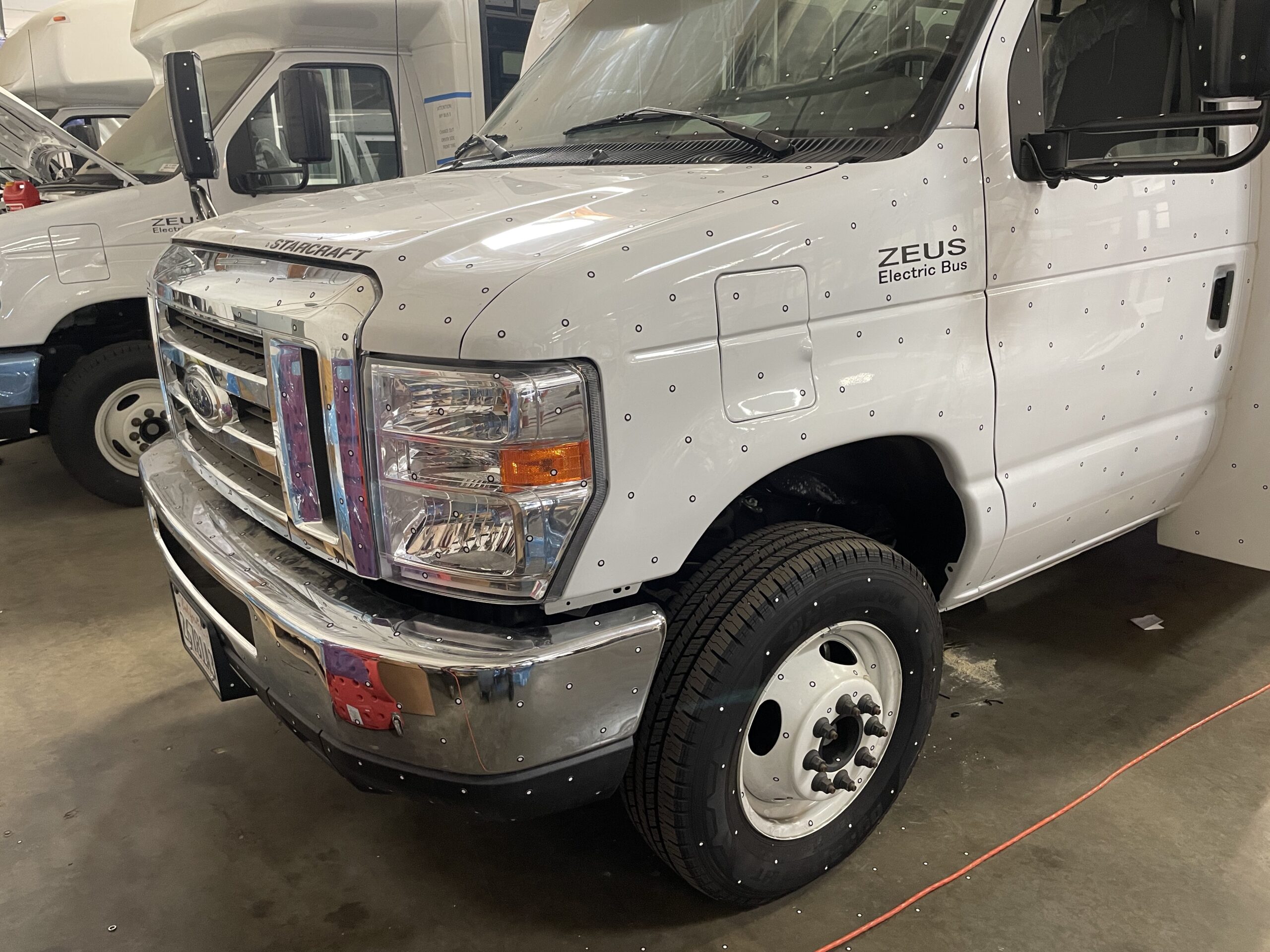
A technician scans the physical part using a handheld laser scanner. The scanner emits a blue laser and uses triangulation, measuring the distance between reference points across the surface, to capture the object’s geometry as a dense cloud of data points. For complex parts, small adhesive targets (6mm dots) are placed on the surface to help the scanner stitch together multiple scan passes accurately.
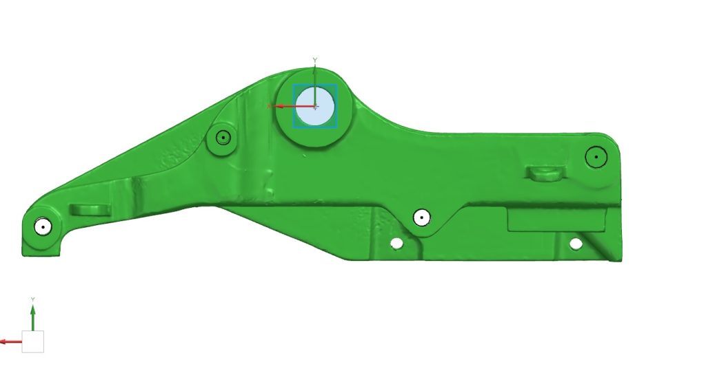
The result is a point cloud, which is processed into a mesh file, typically an STL. This mesh is an extremely detailed digital representation of the object, accurate to 0.02mm in many cases. It captures every contour, radius, and surface feature of the original part.
2. Reverse Engineering
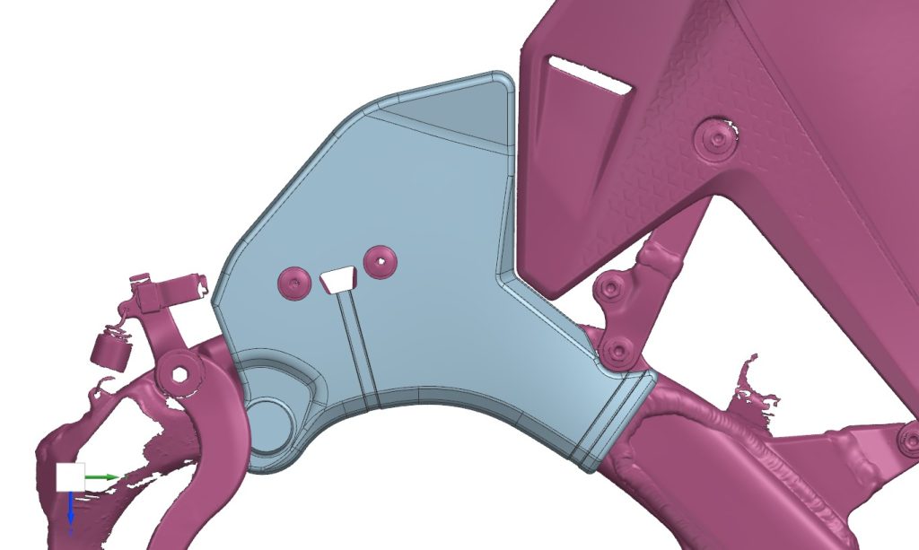
This is where the real engineering work happens, and it’s also where most of the variability in quality comes from. A CAD engineer uses the mesh as a reference to rebuild the part from scratch inside CAD software. At Tangent, that means SolidWorks.
The engineer doesn’t trace the mesh. They interrogate it. They identify planes, establish datums, extract dimensions, and reconstruct the design intent using real geometric features: extrusions, revolves, sweeps, fillets, holes, and bosses. The mesh tells you where surfaces are. The engineer figures out why they’re there and rebuilds them with manufacturing intent intact.
This step requires someone who understands how parts are made, not just how they look. A fillet that appears organic in scan data might be a 3mm radius applied for stress relief. A tapered bore might be intentional draft for injection molding. Getting these calls right requires manufacturing experience, not just CAD proficiency.
3. STEP File Export
Once the model is rebuilt and validated against the original scan data, checking that dimensions match within tolerance, it’s exported as a STEP file. At this point you have a fully parametric solid model that opens cleanly in any major CAD platform, is ready for CNC machining or mold tooling, and can be modified by any engineer on your team.
When Do You Actually Need This?
3D Scan to STEP is the right call in a handful of recurring situations.
Legacy parts with no drawings.
This is probably the most common use case. Equipment that’s been running for 20 years, parts sourced from suppliers who are out of business, components manufactured before digital CAD was standard — when the part breaks and there’s no drawing, scanning is how you get back to ground truth.
Worn or modified tooling.
If a mold, fixture, or tool has been hand-modified over time and drifted from its original spec, scanning gives you a current-state model to work from, whether you’re making a new tool or requalifying the existing one.
Competitor or reference part analysis.
When you need to understand how a competitor’s component is designed, or when you’re developing an accessory that needs to interface precisely with an existing part, scanning gives you an accurate model to design against. This is legal for interoperability and compatibility purposes in most jurisdictions, though it’s worth consulting counsel if IP boundaries are relevant to your situation.
Prototypes going into production.
A part that was hand-built, a casting that was hand-finished, a component that exists only as a physical sample — when you need to take it to production, you need a STEP file. Scanning is how you bridge from physical to manufacturable.
Quality and fit verification.
Sometimes the question isn’t how to manufacture something, it’s whether a manufactured part matches spec. Scan data compared against a nominal STEP model gives you a deviation map showing exactly where a part diverges from design intent.
What Makes a Good 3D Scan to STEP File?
Not all STEP files produced from scan data are equal. Here’s what to look for when evaluating quality.
Clean solid geometry, not a converted mesh. Some workflows simply wrap a mesh in a STEP container. The file extension says STEP but the underlying geometry is still mesh-based. A proper STEP file has solid, parametric geometry you can dimension and modify. If you open it in SolidWorks and can’t add a feature or pull a dimension, something went wrong upstream.
Toleranced features, not approximated ones. Holes should be properly sized, not approximated circles reconstructed from scan noise. Parallel faces should be actually parallel, not within 0.3 degrees of parallel because the scanner had a slightly off angle. An experienced reverse engineer corrects for scan artifacts and applies design intent where the data is ambiguous.
Appropriate file size. A bloated STEP file, particularly one with an enormous number of surface patches, is usually a sign the mesh was converted rather than properly rebuilt. A clean mechanical part should produce a compact, efficient file.
Dimensional verification. The best shops will provide a deviation report showing how the STEP model compares to the original scan data, giving you documented confidence that the reconstruction is accurate.
How Long Does It Take?
Turnaround depends primarily on part complexity, not part size. A simple bracket or housing, even a large one, can often be reverse engineered and delivered as a STEP file within one to two business days. A complex assembly with multiple interacting features, tight tolerances, or intricate internal geometry may take a week.
Rush timelines are frequently possible. Tangent has completed 3D scan to STEP projects over a weekend when the schedule demanded it.
Pricing for reverse engineering services is typically quoted on an hourly basis, with an estimate provided upfront after reviewing part photos or the physical part itself. Most projects are quoted same-day.
STEP vs. Other File Formats: A Quick Reference
Since format questions come up on almost every project, here’s a straightforward breakdown.
STEP (.step, .stp) is the default choice for manufacturing, CNC machining, tooling, and sharing across CAD platforms. If you’re unsure what to request, start here.
IGES (.igs, .iges) is an older neutral format still accepted by some legacy systems. It’s less robust than STEP for solid geometry transfer, but useful if a vendor specifically requires it.
XT (Parasolid) is SolidWorks’ native kernel format. It offers extremely clean geometry transfer between SolidWorks environments and is a good choice if your team works primarily in SolidWorks.
STL and OBJ are mesh formats suited for 3D printing or visualization. They are not appropriate for manufacturing or modification. These are the raw output of the scanning process, not the finished deliverable.
SLDPRT is the SolidWorks native part file format. It’s fully feature-based and editable within SolidWorks, which makes it useful if you want the full parametric model tree rather than just geometry.
If you’re unsure which format your manufacturer or downstream team needs, ask before the project starts. Good reverse engineering services can export to multiple formats from the same model, so getting it right is usually just a matter of knowing what to request.
What to Send to Get Started
To get a quote for a scan to STEP project, most shops need the following:
Photos of the part from multiple angles, rough overall dimensions (ballpark is fine), the intended use for the STEP file whether that’s manufacturing, modification, or analysis, and any tolerance requirements or critical features worth flagging upfront.
If the part is too complex to quote from photos alone, a short consultation call usually resolves it. The more context you provide about what the file needs to do, the better the outcome. Reverse engineering involves judgment calls at every stage, and knowing your end goal shapes how those decisions get made.
The Bottom Line
A STEP file is the entry ticket to manufacturing. If you have a physical part and need to get it into production, into a CAD system, or into a design review, scan to STEP is the most reliable and precise path to get there.
The scan captures exactly what exists. The reverse engineering turns that into something you can actually use. And the STEP file travels anywhere.
If you have a part that needs to become a file, get in touch with our team at Tangent Solutions for a free estimate. Most projects are quoted same-day.