Reverse engineering has long been synonymous with painstaking disassembly work using traditional tools. However, the landscape is rapidly evolving, and 3D scanning for reverse engineering is revolutionizing the way we understand and recreate mechanical components.
 3D laser scanning technology can produce highly accurate and editable 3D models without the need for manual disassembly, ushering in a new era of efficiency in production methods, quality control systems, and file creation; without taking out the calipers.
3D scanning for reverse engineering provides multiple benefits, making this technology ideal for efficient production methods, quality control systems, and file creation.
Let’s cover the bases on how to use 3D scanning for reverse engineering with the use of a handheld 3D laser scanner, to gain an understanding of the process.
What is Reverse Engineering?
Reverse engineering, in terms of using scan data, is a process that involves creating a digital representation or model of an existing physical object or component.
Digital representations are created during 3D laser scanning into a mesh file, commonly STL. A mesh refers to a digital representation of the surface geometry of a three-dimensional object and this mesh is what is needed to start the reverse engineering process.
The mesh is highly accurate in dimension, geometries, and shape. This accuracy guarantees the accuracy of the 3D model, in CAD format, which can be used in various industries including manufacturing, aerospace, quality control, architecture, and art restoration, among others.
What is 3D Laser Scanning?
3D laser scanning is a technology used for capturing the precise three-dimensional shape and spatial information of objects, environments, or surfaces using laser beams.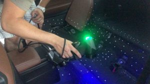
It is a non-contact and non-destructive method for generating highly accurate 3D models of real-world objects, offering a valuable tool for preserving and improving upon existing designs, products, or artifacts and is particularly useful when dealing with complex geometry.
3D laser scanning is valued for its speed, precision, and ability to capture complex shapes and large areas with high accuracy. It has become an essential tool in various fields for data capture and modeling purposes.
The 3D Scanning for Reverse Engineering Process
The process of 3D scanning for reverse engineering involves capturing detailed and accurate 3D data of a physical component in order to create a digital models, like CAD files, that can be used for various purposes, including product design, analysis, and manufacturing.
Below the process is broken down into 5 phases:
-
Prepare the Surface For 3D Scanning
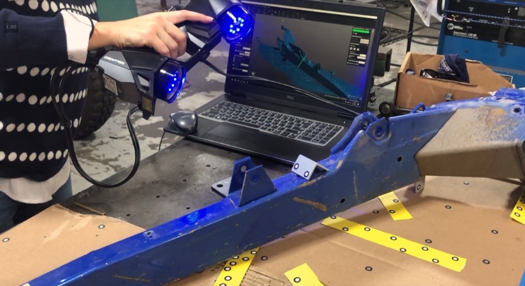
The first stage of a 3D scanning process is data acquisition through the scanner. The object that will be scanned needs to be cleaned of dirt, debris, or any unwanted data as a scanner will record everything it sees.
In short, 3D scanning is performed by a series of lasers shooting out from the scanner and reflecting off targets; small stickers that are placed all on the object.
If a part is transparent or reflective, it can be sprayed with a powder-like substance to take away that reflectivity. Doing that can improve the accuracy of results and make sure unwanted objects aren’t reflected back to the scanner. -
Starting the 3D Scanning Process
After the object is prepared, the scanner is calibrated. Calibration is essential before performing a laser scan as it determines the correct values based on the environment. By using a calibration table, volumetric accuracy, light, and resolution are recorded.
From there a tech will prepare the scanning resolution based on the size of the project. Smallest detail for smaller components and larger for bigger projects that do not require minuscule details. For example, scanning anywhere from 1 to 5 millimeters on a large boat.
Choosing the right size is also key to keeping file sizes efficient along with not maxing out CPUs of the scan computer.
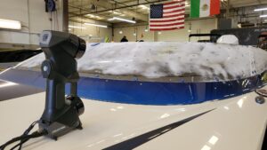
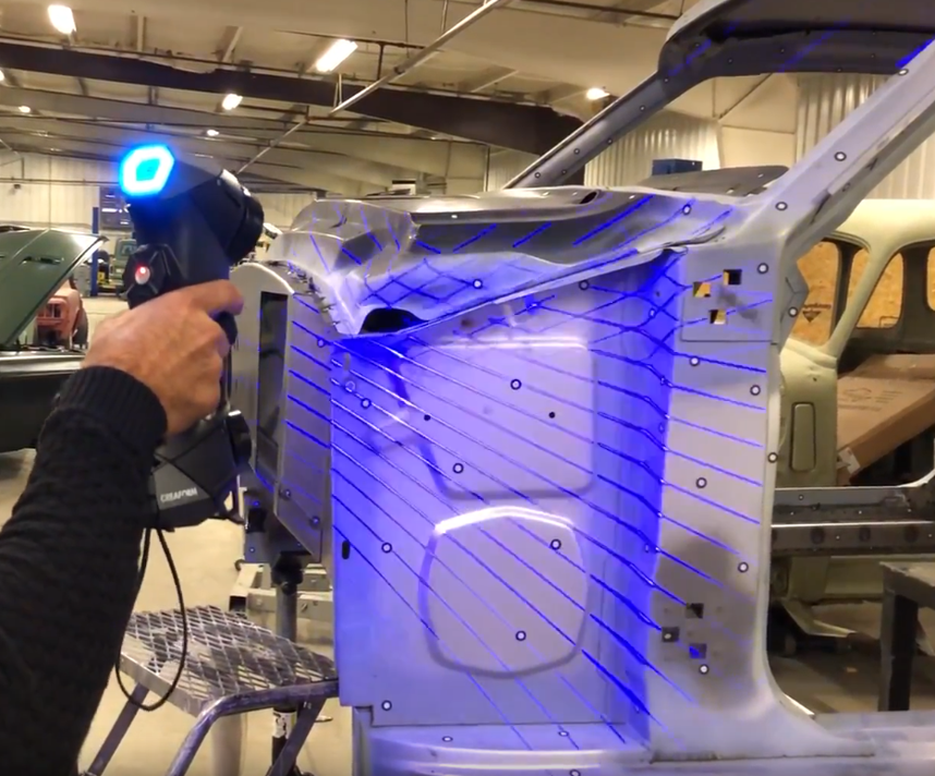
As the laser scanner is activated, highly accurate laser are shot out from the scanner, over the physical objects, and reflect off the targets to create a digital mesh.
When the laser beams traverse a physical object, they gather data points organized into a sequence of triangles, providing information about the object’s elevation, range, and thickness. This technique is commonly referred to as triangulation.
-
Refining 3D Scan Data
Depending upon the goals of the project or the size, a scan technician may need to perform the scan process again. This occurs on large projects where the underside cannot be viewed or for projects that cannot bear their own weight, causing a flex in the project.
Any movement of the object will cause a discrepancy in the scanning process resulting in incorrect measurement. When a scan is performed twice, the sides are labeled to then perform a merge process.
The refining of a 3D scan requires multiple scans of the same object to collect every detail. Initially, the scan creates the mesh that gathers all major surfaces and features of the object. However for tiny details, a single laser mode is activated and go over the detail needed, slowly.
Subsequent scans will register the finer details of the object, delivering the best scan with highly accurate mesh sizing.
-
Convert to Mesh File
Once the refined mesh file has been generated, it will need to be post processed.
This step is needed in every scanning project. It allows for the clean up of erroneous data the laser scanner recorded, as the scanner will scan everything it sees and is why the first step of preparing the object for scanning is so essential. The native scanner’s software predictably understands what data is not important and will suggest triangles to delete while also letting the user delete anything.
After clean up, merging, and geometry isolation, the scan data is exported into an STL or OBJ format. These are mesh files and are the files needed to reverse engineer.
-
Scan to CAD File
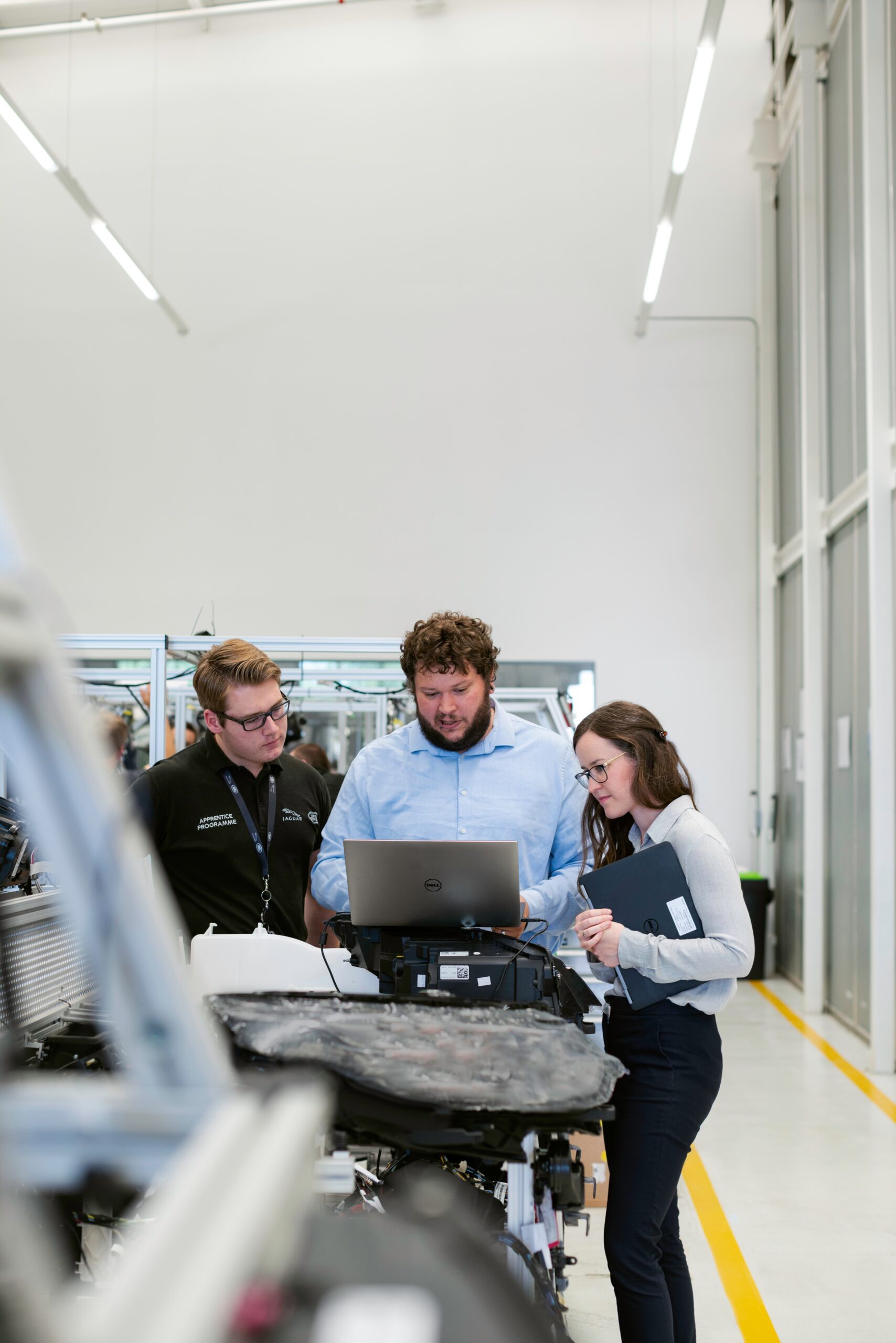
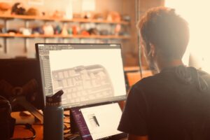
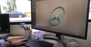
The next step is creating a CAD model from the mesh file. Converting meshes into CAD files is done using reverse engineering software, which depending on the size of the object and the detail, can sometimes take considerable time.
A CAD engineer will create the 3D model based on a scan; identifying geometries, dimensions, and sizes.
Essentially mesh data is the guideline for the reverse engineering process and is correct in measurement.
3D scanning for reverse engineering will create a fully functional CAD model to work with. This data can be used for multiple purposes including running simulations, data analysis, and manufacturing processes relevant to the project’s specific application.
Reverse Engineering Industries
With the highly accurate scan data from 3D laser scanning, physical objects can be transformed into a digital model. In the past, engineers had to manually dismantle products to replicate the assembly in CAD software.
This process has been replaced with more efficient laser scanning, enabling users to directly transfer the shape and physical attributes of a product to design software.
Reverse engineering is essential for multiple applications including manufacturing, research and development, automotive, and aerospace; among other industries. Due to its convenience and variety of applications, 3D laser scanning is a pivotal engineering tool.
The versatility of 3D scanning for reverse engineering extends across various industries and needs including:
Analysis and Modification:
Once the digital model is created, it can be analyzed, modified, and manipulated using various software tools. Engineers and designers can make changes, improvements, or adaptations to the digital model as needed.
Documentation:
Reverse engineering provides a means to document existing objects or components that may lack comprehensive design documentation. This is particularly valuable for legacy parts or products.
Reproduction:
The digital model can be used to reproduce or manufacture exact replicas of the original object or component using various manufacturing techniques like 3D printing, CNC machining, or injection molding.
Quality Control
Reverse engineering can be used for quality control and validation. By comparing the digital model to the original object, discrepancies or defects can be identified and corrected.
Innovation and Improvement:
Reverse engineering can lead to innovation and improvement in design and functionality. Engineers can study existing products to gain insights into how they work and find ways to enhance or optimize them. 
One example of an industry that finds 3D scan data invaluable is aerospace. The amount of attention to detail needed that each component needs in an airplane’s assembly, is unmatched to any other field. Validation of fitment, quality, and integrity can be the difference between a plane with thousands of hours of fly time, or an aviation disaster.
Solving Challenges by 3D Scanning for Reverse Engineering
Reverse engineering with scan data is widely used in various industries, including manufacturing, aerospace, automotive, architecture, and art restoration, among others. It offers a valuable tool for preserving and improving upon existing designs, products, or artifacts and is particularly useful when dealing with complex or undocumented objects.
Laser scanners can enable precise 3D modeling of large objects and small objects. The scanned data can be used for CAD designs with numerous possibilities for refining and reproducing quality parts.
When it’s imperative that each measurement and dimension is as precise as possible, 3D scanning for reverse engineering is reliable technology. It is now easier and faster to create 3D models.