Have you thought of using a 3D laser scanner to create a 3D mesh to CAD?
Using a 3D laser scanner for reverse engineering offers the advantage of precise transformation of a mesh to CAD, making it a valuable tool in various industries.
Reverse engineering involves analyzing an existing object or product to understand its design, structure, and functionality in order to recreate, modify, or improve it. 3D laser scanning greatly accelerates the creation of a CAD file from a mesh; the export of 3D scan.

How do you convert mesh to CAD from a 3D scan file? Why can’t a 3D laser scanner create a CAD model initially?
These are common questions from many clients and engineers who may not be familiar with 3D laser scanning.
First off, I will explain the reverse engineering process in terms of being paired with a 3D laser scanner.
An Overview of Mesh to CAD Conversion
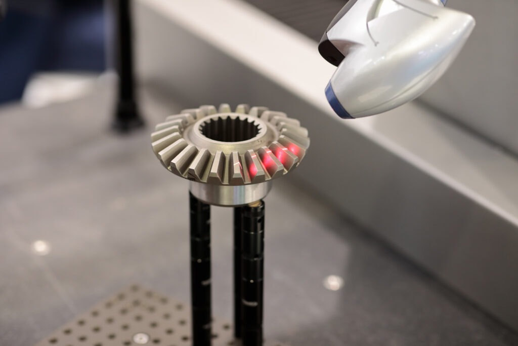
Reverse engineering is the powerful process that allows designers to create digital models of physical objects. Paired with 3D laser scanning services, the instant digitalization and mesh to CAD conversion of an object is performed by a series of lasers.
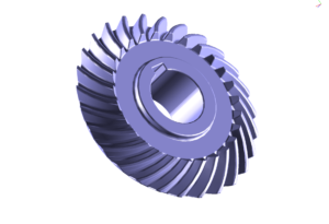
As the lasers pass over a physical object, the data is recorded in a series of triangles understanding the height, distance, and depth of the object. This process is also known as triangulation.
The immediate export of mesh data is an STL or OBJ file. STL files are essentially only a representation of the object. A crucial step in the reverse engineering process is redrawing the object using the mesh as a guide.
What is Reverse Engineering?
Reverse engineering is the transformation of the mesh data that is created during 3D laser scanning, into a precise and editable CAD file.
 Reverse engineering involves extracting design information from existing physical objects and creating digital representations of
them.
Mesh to CAD conversion plays a pivotal role in this process, allowing designers to obtain accurate CAD models from 3D scanned or digitized mesh data.
In our company, design engineers draw a CAD file based on the mesh data with ultra precision. The team creates hole diameters, radii, edges, shapes, and more with the guidance of an STL file.
The exports created post mesh to CAD conversion are STEP, IGES, and XT format. These universal formats are what is needed to enable designers and engineers to analyze, modify, and manufacture existing physical objects with ease and precision.
Understanding Reverse Engineering and Mesh to CAD
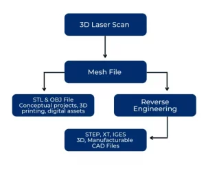
It is a common misconception that a 3D laser scanner can initially create a CAD file straight from a scan.
Our team is asked this question daily. We do enjoy the opportunity to educate our clients and have created a flow chart and sample folder, with common file deliveries that highlight the mesh to CAD conversion.
Benefits of Mesh to CAD Conversion in Reverse Engineering
Why are CAD files needed for most engineering projects?
CAD files are essential for most engineering projects due to their numerous benefits and the critical role they play in the design, development, analysis, and manufacturing processes.
Here are some of the most popular benefits of CAD files:
-
Design Iteration and Improvement:
Mesh to CAD conversion enables designers to make modifications to captured geometry easily. This flexibility facilitates iterative design processes, allowing for the enhancement of existing designs and the creation of improved versions.
-
Analysis and Simulation:
CAD models obtained through 3D laser scanning can be used for finite element analysis, FEA, and other simulations.
This capability aids in evaluating the performance and structural integrity of existing objects, providing insights for optimization and refinement. -
Manufacturing Replication:
With precise CAD models resulting from conversion, manufacturers can reproduce existing objects accurately.
This replication process is crucial for industries that require the reproduction of legacy parts or objects. -
Integration with CAD Workflows:
Converting a mesh to CAD format allows seamless integration with various CAD software tools and workflows.
Designers can leverage the power of CAD features, such as parametric modeling and assembly design, to further refine and optimize the captured geometry.
Optimization Strategies for Mesh to CAD Conversion
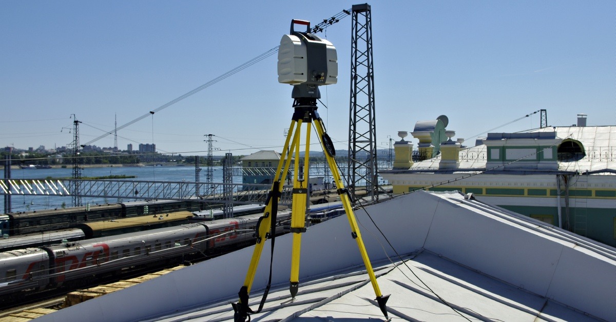
Once scan data has been recorded, all data has to be post processed. Post processing includes the elimination of unwanted data, merging multiple files if needed, and orientating the file on an XYZ plane.
The lasers on a scanner record everything in the environment; the table it sits on is a common delete.
Post processing validates that a project only includes what is important. This helps keep down computing times especially with large projects. Here are some other strategies to create optimized CAD files:
-
Mesh Cleanup:
Prior to conversion, the mesh data should undergo cleaning and optimization to remove noise, holes, and non-manifold geometry.
The scanner’s native software can assist in this cleaning process, ensuring a smooth and accurate conversion. -
Feature Extraction:
Reverse engineering often involves capturing specific design features of an object.
Feature extraction techniques allow designers to identify and extract key geometric elements, such as holes and complex curves, from the mesh model and convert them into parametric CAD features. -
CAD Model Optimization:
Once the mesh has been converted into a CAD model, optimization strategies can be employed to enhance the design.
Techniques like topology optimization, which analyze and remove unnecessary material, can lead to lightweight and structurally efficient CAD models.
Top Reasons to Convert a Mesh to CAD
The main reason our clients ask for CAD files after a 3D scan is manufacturing.
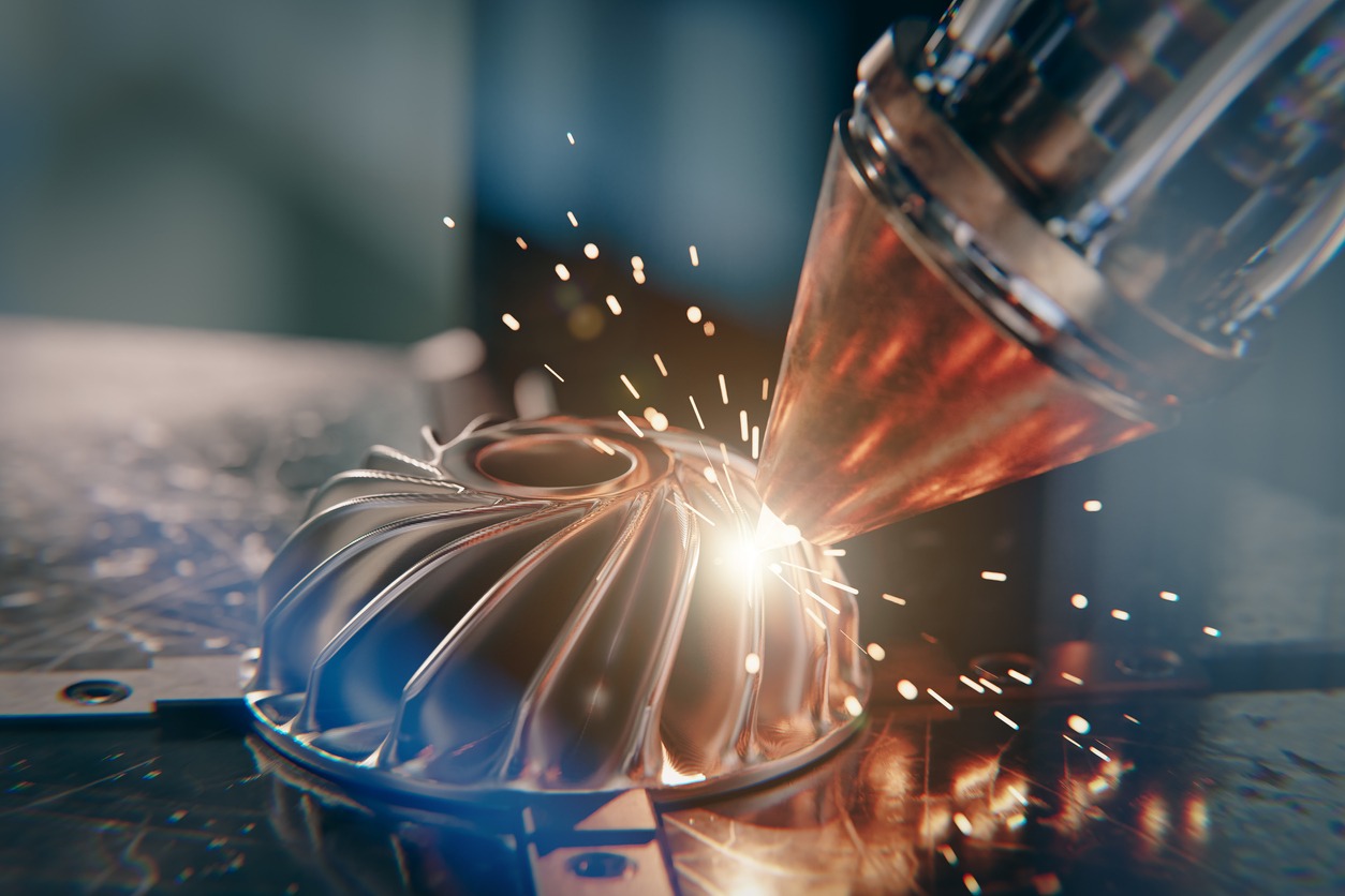
Manufacturing processes such as machining, laser cutting, injection molding, and other processes need a CAD file in order to code the proper toolpath generation of their machines.
For processes like CNC machining and 3D printing, CAD files are used to generate tool paths and instructions for the manufacturing equipment.
These tool paths guide the machinery in shaping and fabricating the physical object according to the design.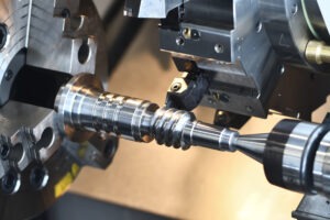
Manufacturers also use CAD models to simulate the assembly process, checking for interferences, clearances, and proper fitment of components.
This ensures that the final assembly will come together smoothly and without unexpected issues.
Summarizing the Mesh to CAD Conversion
Reverse engineering, empowers designers and engineers to recreate physical objects digitally. Through this process, existing objects can be analyzed, improved, and replicated with accuracy and efficiency.
Understanding the benefits and techniques involved in mesh to CAD conversion, allows for seamless integration of reverse engineering into the design workflow, enabling design iterations, analysis, and manufacturing replication.
By converting the mesh to a CAD format, designers can easily modify and refine the captured geometry, facilitating design improvements, analysis, and manufacturing.
As technology continues to advance, the field of reverse engineering will evolve, providing even more sophisticated tools and techniques.
Staying abreast of these developments and exploring innovative approaches will help designers harness the full potential of reverse engineering, opening doors to exciting design possibilities and efficient manufacturing processes.
Embrace the power of mesh to CAD conversion in reverse engineering, and embark on a transformative journey of recreating physical objects in the digital realm with precision and creativity.