The benefits of evolving technology specifically for fiberglass companies, includes 3D scanning for fiberglass, mold making, and CAD design.
Providing a fiberglass project with accurate and detailed digital representations of objects, leaps and bounds over the original process of handmade mold making. 3D scan data facilitates precise measurements and quality assurance opportunities to deliver the best product for fiberglass companies.
This article explores the benefits of employing 3D scanning for fiberglass molds, shedding light on its unmatched capabilities.
How Were Original Fiberglass Molds Made?
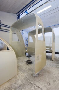
Traditionally, fiberglass molds were made by hand. Creating a fiberglass mold is a meticulous process that involves several key steps. It begins with the development of a master pattern, crafted from materials like wood, foam, or clay, accurately representing the final product’s shape.
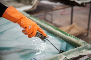
The master pattern is then coated with a gel coat to provide a smooth finish and act as a barrier. Layers of fiberglass mat or cloth are applied over the gel coat, saturated with resin to form a robust composite structure.
Following the application, the fiberglass layers undergo a curing process, which may involveheat to expedite hardening. The cured fiberglass mold is carefully separated from the master pattern, and excess material is trimmed.
The mold’s surface is meticulously finished to ensure a precise and smooth mold. Reinforcements or support structures may be added for durability, and a final inspection is conducted to meet quality standards.
Before each use, a mold release agent is applied, facilitating easy separation during the molding process. The completed fiberglass mold is then ready for reproduction, allowing for the creation of multiple identical products with accuracy and efficiency.
This process is old-school, messy, and tedious.
How is 3D Scanning for Fiberglass Projects Beneficial?
New technology, including 3D laser scanning, allows the cutting of foam by CNC machines to create the molds. 3D scanners can record any physical surface to be reverse engineered to a CAD model.
CAD models including STEP, IGES, or XT format are the files needed to program a CNC machine on how to cut a mold. The resulting models are highly exact dimensionally thanks to 3D laser scanning.
How Are Fiberglass Molds Cut By CNC?
CNC machines are employed for cutting foam due to their precision, and the process involves several systematicsteps.
Initially, a CAD file is created to define the desired foam shape, encompassing geometric details essential for the CNC machine’s operation.
From there, Computer-Aided Manufacturing, CAM, software converts this CAD file into toolpaths and generates G-code, a set of instructions guiding the CNC machine on foam cutting procedures.
Before cutting begins, the foam material is securely fixed to the CNC machine’s worktable, ensuring stability throughout the cutting process. The s election of an appropriate cutting tool, depending on foam type and design intricacy, is a crucial step.
The machine then executes the cutting process by meticulously following the toolpaths outlined in the G-code.
Quality control is integrated throughout the operation, with operators monitoring the machine and periodically inspecting the foam to ensure accurate cuts aligning with design specifications.
CNC foam cutting is highly advantageous for creating intricate and precise shapes, making it a preferred method in various industries such as packaging, automotive, aerospace, and the production of foam inserts for protective packaging.
Its efficiency and accuracy make it a valuable tool in the manufacturing process of foam components.
3D Scanning for Fiberglass Mold Measuring
Traditional mold measuring methods often involve manual processes using contact measuring tools. However, these methods present challenges when dealing with surfaces’ curvature and concave structures.
As mentioned above, an operator will continuously monitor the mold making to catch any mishaps. Not everything can be caught though.
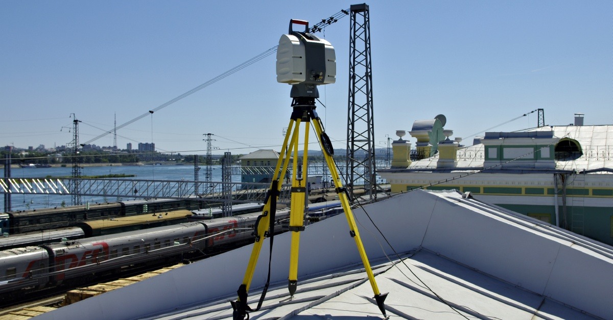
Enter 3D laser scanning technology, which has become a primary method for mold inspection and measurement. The mold can be 3D scanned to generate data to be compared to the initial CAD model. Tolerances are identified and a visual map will highlight any issues.
Quality Assurance
How accurate is 3D scan data? Depending upon the scanner used, data can be recorded down to the micron.
Different technologies, such as laser-based scanners, structured light scanners, and photogrammetry, offer varying levels of precision. Laser scanners, renowned for their high accuracy, are often preferred for applications demanding meticulous measurements in industrial settings.
Structured light scanners and photogrammetry, while slightly less accurate in comparison, remain suitable for a broad range of applications.
Based on the ability to record at such a high amount of precision, fiberglass companies can also validate the quality of their molds and fiberglass projects. Many scanning platforms are accompanied by data verification systems.
The ability to compare scan data with existing CAD models assures quality of a product. Opting for higher resolution settings generally yields more detailed and accurate scan data, although it may necessitate additional time and resources.
File Requirements for Fiberglass Molds
To seamlessly integrate 3D scan data into the fiberglass manufacturing process, specific file types are crucial. The scanning process generates point cloud data, which is then converted into CAD data.
This process is called reverse engineering. This surface reconstruction process replaces scan points with CAD-capable surfaces, creating a solid model ready for mold construction.
The mesh to CAD conversion is the most time consuming process but will deliver the usable files. Files deliveries for mold making, including other forms of manufacturing, include STEP, IGES, and XT.
What Industries Use 3D Scanning for Fiberglass?
Several industries leverage 3D scanning for fiberglass applications, harnessing its capabilities for improved efficiency, precision, and innovation.
Automotive
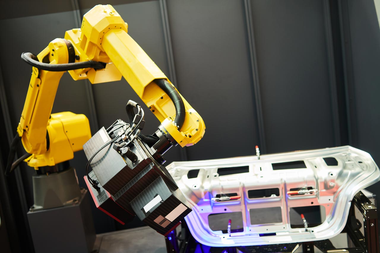
The automotive industry extensively employs 3D scanning for fiberglass in the design and manufacturing of vehicle components.
Fiberglass bodies for prototyping, fluid dynamic testing, and racing are a couple to mention.
Aerospace
3D scanning aids in the precise fabrication of intricate parts, allowing for optimal aerodynamics and structural integrity. Additionally, the technology is best for quality assurance and maintenance inspections in the aerospace sector.
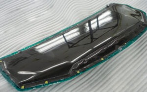
Marine and Boat-Building
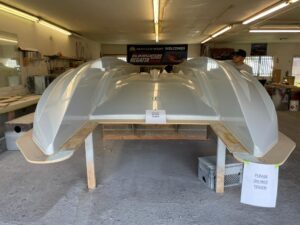
The marine and boat-building industry utilizes 3D scanning for fiberglass applications in the design and construction of boats and marine components.
The technology facilitates the creation of detailed molds, ensuring that each component fits seamlessly, contributing to improved vessel performance and durability.
Read up on a project of taking a handmade boat mold to usable CAD files.
Architectural
3D scanning is employed for creating detailed replicas of architectural elements made from fiberglass. This is particularly useful in heritage restoration projects, where accurate reproductions of intricate fiberglass components are essential for preserving the original design aesthetics.
Entertainment
Furthermore, the art and entertainment industry utilize 3D scanning for fiberglass in the production of props, sculptures, and set designs.
The technology allows for the precise replication of complex shapes and intricate details, enhancing the overall visual impact of artistic creations.
Conclusion
The integration of 3D scanning for fiberglass projects is a game-changer, offering unparalleled benefits in quality assurance, file optimization, and mold measurement.
As the industry continues to evolve, embracing these innovative technologies becomes imperative for those seeking to stay ahead in the competitive world of fiberglass manufacturing.