3D laser scanning is a revolutionary engineering tool for digitizing surfaces into usable data. Scan data is commonly used for data verification purposes but users can also 3D scan for CNC machined parts production.
How do you 3D scan for CNC machined parts? What is the process of creating files ready for machine programming?
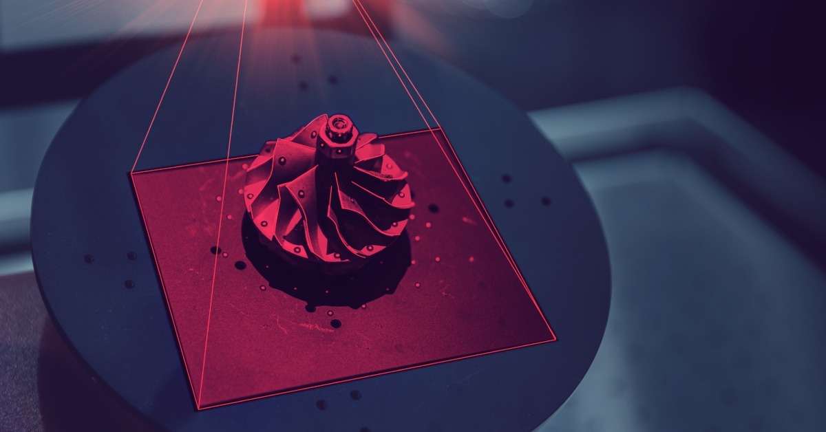
The 3D scanning process is performed by 3D laser scanners that range in accuracy. The latest 3D scanners record data at a high rate of speed and also deliver files with a high level of accuracy; down to the micron.
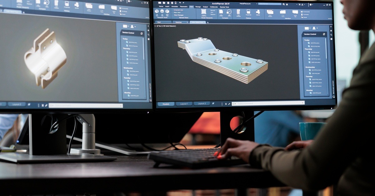
This data is essential for the creation of CAD files which are 3D models that represent the technicality of a part including complex geometry, ID, OD, and other dimensions. All of this data is needed to 3D scan for CNC machining.
Schedule a Free Consultation on 3D Scanning Services for CNC Machining
What is the 3D Scanning Process?
3D laser scanning is broken down into preparation, scanning, and post processing. The scanning is the fastest portion of the entire operation but proper prep and post processing will help our Design Engineer reverse engineer a 3D scan for CNC, faster.
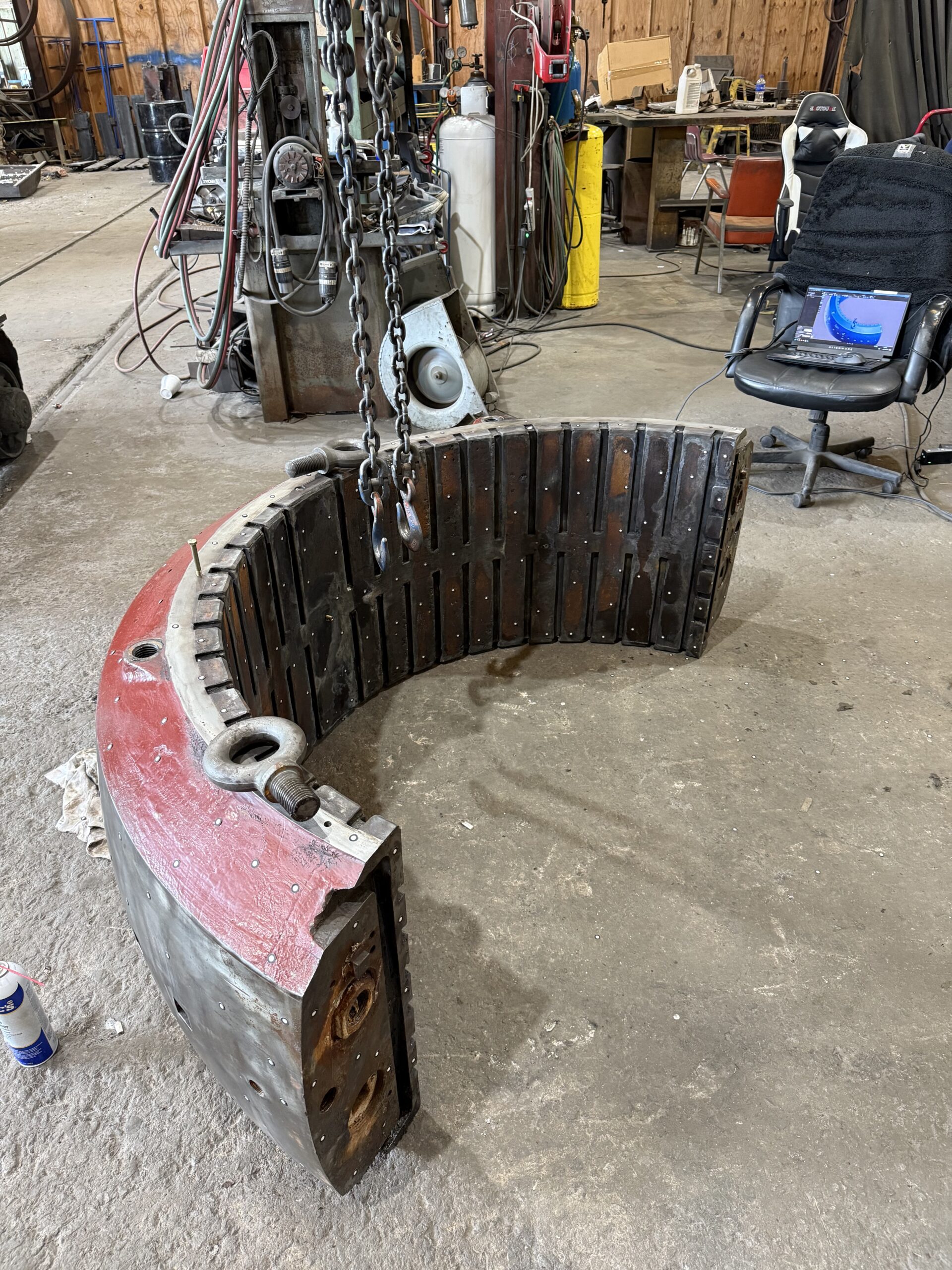
The part that is being selected to 3D scan for CNC machining is placed on any surface. A flat, clean surface is preferred as it cuts down on the clean up process. It is free of debris or components that are not needed in the design and is then prepped with 6mm targets. 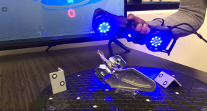
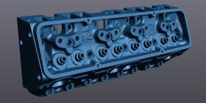
During preparation, targets are placed throughout the project. Scan targets are small adhesive circles that the laser scanner’s laser will reflect off of and back to the scanner to create a mesh.
This mesh represents the change in height, shape, and curvature of the surface it sees; a process called triangulation. Scan targets are removed after the 3D scan for CNC is performed and do not leave a residue.
Read more: A Beginner’s Guide to 3D Laser Scanning
Before any 3D scan for CNC or other project, the laser scanner is calibrated to its environment with a calibration pad. This validates its accuracy and makes sure the scanner is working properly.
By simply clicking, the scanner is turned on and the operator begins to record the project. Scan data is recorded instantly on screen as a way to also validate the data is collected fully.
After the operator is satisfied with the mesh created, post processing will be completed to delete unwanted data like the surface the project sat on or other features in the scene. Deleting data that is not needed cuts down on file creation time.
How to 3D Scan for CNC Specifically
When the project is used to 3D scan for CNC file creation, important geometry will need to be represented. Our technicians discuss project goals before scanning commences in order to validate the correct data is collected. This is especially important for manufacturing as a variance in hole size can trash an entire production.
After clean up has been completed, the technician will then highlight surfaces, make planes, and represent hole dimensions. All of this data will be imported into reverse engineering software which is the next step to create a CAD file.
3D scanning services for CNC at a glance.
Reverse Engineering to CAD
Is it a common misconception that mesh files are CAD files. A mesh file is essentially a “picture” of the project. It is simply just a representation and is not a parasolid. A parasolid is modeled file that will represent all of the geometry collected during the scanning process.
Mesh files are not good for manufacturing. These files do not tell the machines how big a hole dimension needs to be or how long a surface is.
A deeper look at the Mesh to CAD Conversion.
In order to create a CAD file from a 3D scan for CNC applications, the scan data must be reverse engineered. The reverse engineering process uses the mesh data created in the scanning process to draw the CAD file.
Reverse engineering is the most time consuming of the entire Scan to CAD procedure but produces usable files that are ready for machining and other manufacturing processes.
If you need clarification on the difference between a CAD file and a mesh file, here is a link to a sample folder of common exports of the 3D scanning process.
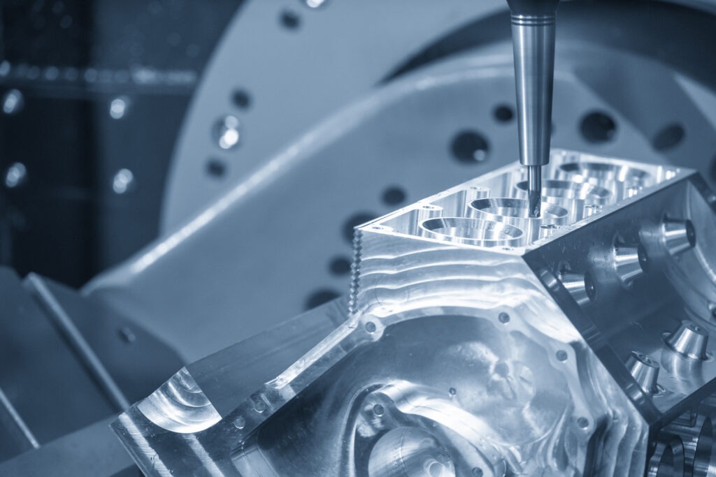
Converting 3D Scan for CNC to Machining
When a CAD file is created it can then be passed along to any machinist to run through their machining program. Common exports from our company include STEP, IGES, and XT. These files are universal and are able to be opened by anyone with CAD software.
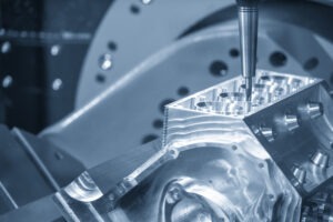
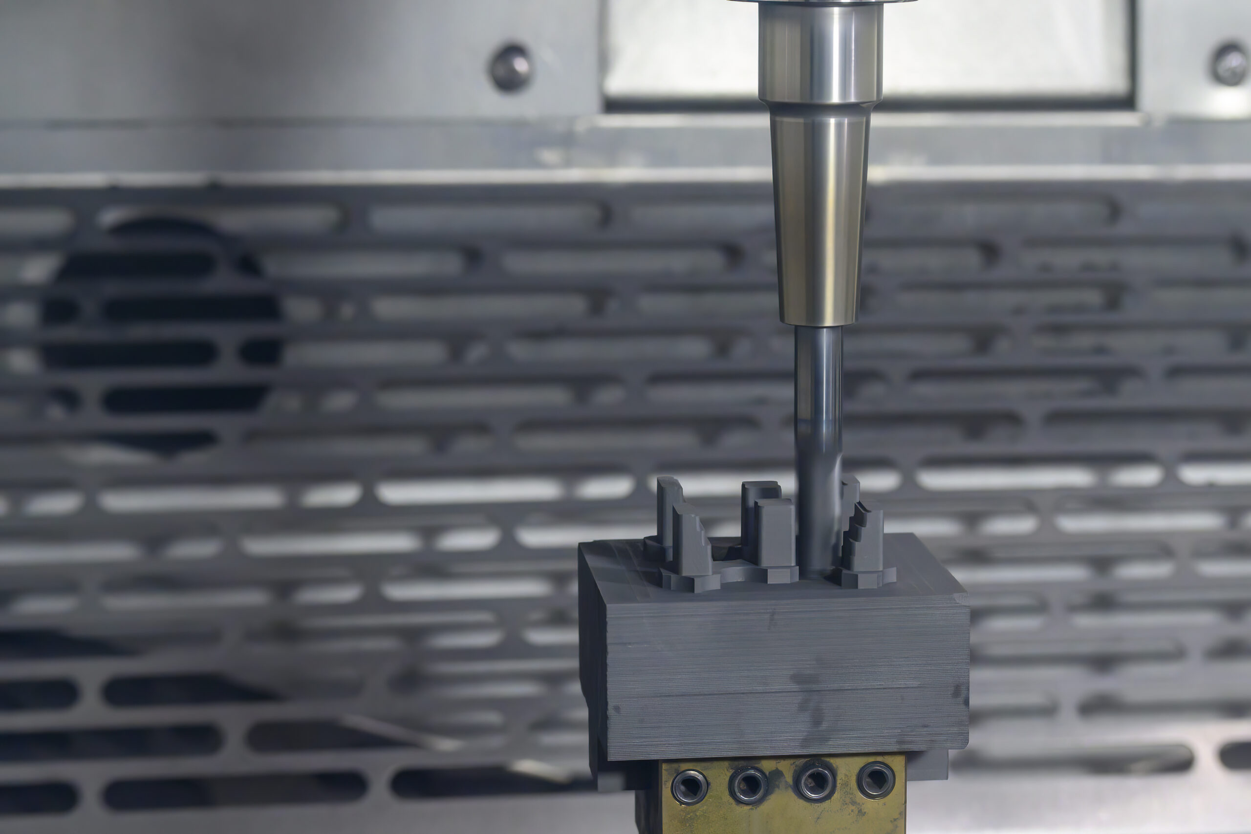
The machining program of choice will depend upon the machining company. A common software is Mastercam. This software is used in a variety of machines including lathes, routers, 5-axis, mills, and more.
The CAD file created from 3D scan for CNC is imported and the software will tell the machine what action is needed to produce the part. Reverse engineering is the one of our most desired services in our business, because of our understanding of CNC machining.
What is great about CAD files is the ability to change the design quickly. The machinist may recommend a design tweak in order to cut down on production and material costs. Our design team can make an edit and resubmit within a few minutes.
Post Production Verification
3D laser scanning provides such a high level of accuracy that data can be used to verify the machining process after production. When data from a 3D scan for CNC file creation is created, this level of accuracy is represented in the CAD file.
The CAD file can be compared to a new 3D scan. After the machining process is completed, the project will be scanned and then imposed over the original CAD model. A heat map will be able to show discrepancies that will visibly represent if there is an error in manufacturing.
With the ability to verify production, 3D scan for CNC is also great for quality control methods. Both clients can have faith their products are of the upmost quality and CNC machinist are also able to market their precision ability.
Read more about quality control and data analysis services.
3D Scan for CNC Machining
3D scan for CNC applications elevates both the quality of parts and also the high standard of machining that it took to produce those parts. Although machining may have some specifically only thinking of working with metal, CNC also cuts plastics and wood.
3D laser scanning is the ultimate tool for reverse engineering for CAD file creation. These files assure a level of accuracy that is the standard for the latest engineering projects. Learn more about 3D scan for CNC machining by contacting our company now.