In the expansive universe of 3D modeling and design, two file formats take center stage: CAD and STL.
These formats serve distinct purposes, each contributing uniquely to the world of digital design and manufacturing.
In this exploration, we unravel the nuances of CAD and STL files, delving into their differences and shedding light on the intriguing process of reverse engineering.
Particularly in the context of converting STL files to CAD using 3D laser scanning.
Introduction: CAD and STL Files
You may be asking, what is a CAD file? What is an STL file?
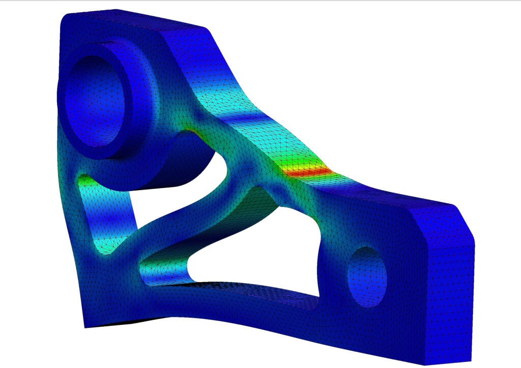
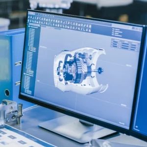
A CAD file (Computer-Aided Design) is a digital file format that contains information used by computer-aided design software to create 2D or 3D representations of objects, structures, or systems.

CAD files serve as the digital blueprints for designs, allowing engineers, architects, and designers to create, modify, and analyze various elements with precision and efficiency.
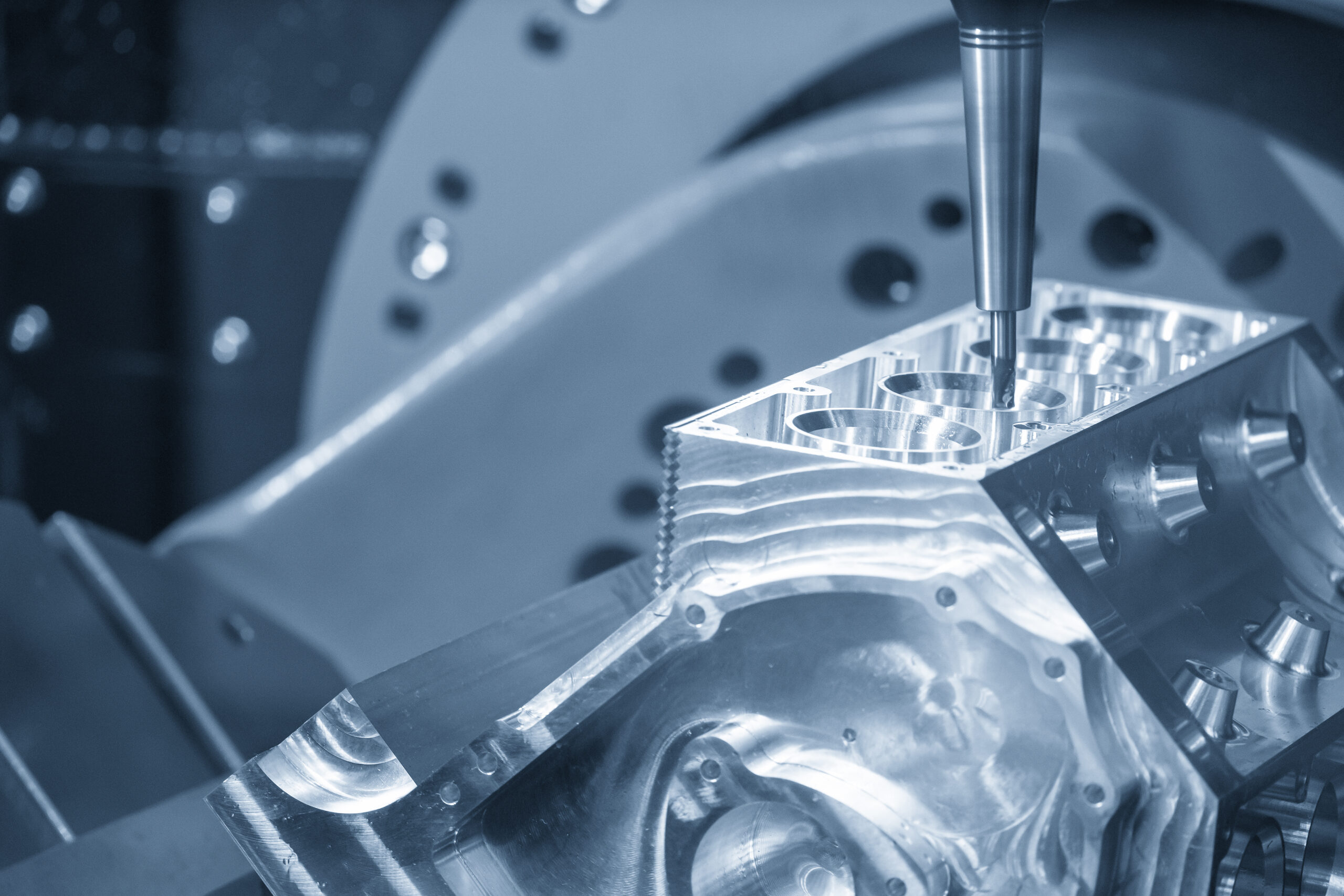
CAD files are imperative to manufacturing because of the parametric information it holds. This data is needed to build the code around the manufacturing process.
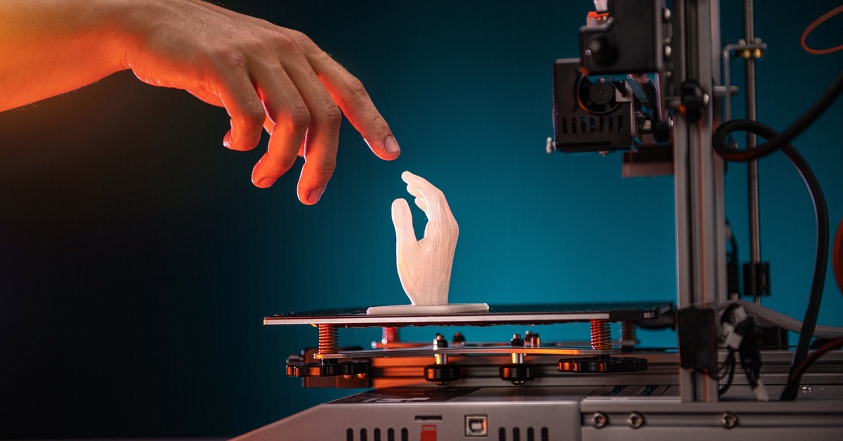
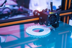
An STL (Standard Tessellation Language) file is a common file format used in conceptual applications and 3D printing.
Unlike CAD files that contain detailed information about the structure, dimensions, and parameters of a 3D model, STL files focus on the surface geometry of the model.
STL files only represent data as a mesh of interconnected triangles.
Understanding CAD Files: The Blueprint of Digital Design
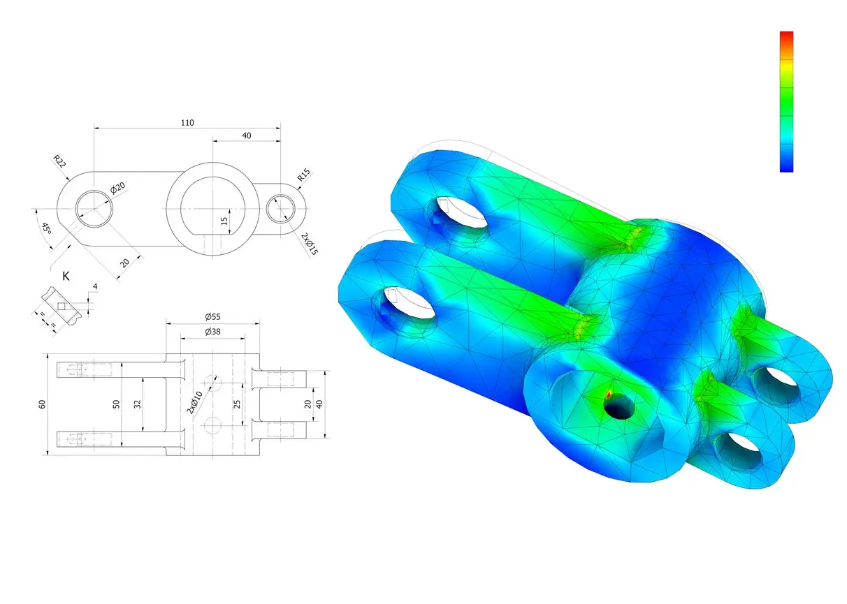
CAD files are the backbone of digital design. They encapsulate precise geometric information, allowing engineers and designers to create, modify, and analyze 2D and 3D models with unparalleled accuracy.
The richness of CAD lies in its ability to store not only the visual aspects of a design but also its underlying parametric data.
This parametric data includes dimensions, constraints, and relationships, offering a dynamic and editable foundation for the design.
CAD files come in various formats such as STEP, IGES, and XT with each allowing a universal file opening.
The versatility of CAD files makes them an integral part of the product development lifecycle, from conceptualization to prototyping and beyond.
Unveiling the STL File: A Mesh of Surfaces
On the other end of the spectrum, we encounter STL files. Unlike CAD files, STL does not store parametric data. Instead, it represents a 3D model as a mesh of interconnected triangles.
This simplicity makes STL files ideal for 3D printing, conceptual purposes, and rapid prototyping.
This is ideal when the focus is on the physical form rather than the underlying design parameters.
STL files, with their straightforward structure, find common use in the additive manufacturing industry. They describe the surface geometry of a 3D object, making them compatible with a wide range of 3D printers.
Bridging the Gap: The Reverse Engineering Process
In the dynamic realm of design and engineering, there arises a need to transition between these two file formats. This is where reverse engineering, particularly with the aid of 3D laser scanning, comes into play.
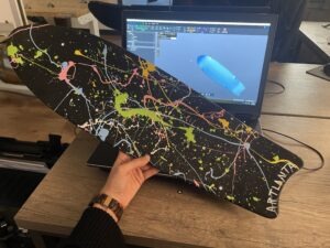
The reverse engineering process involves capturing the physical form of an object using a 3D laser scanner, generating a point cloud or mesh representation of its surface.
Subsequently, this data can be converted into an STL file for 3D printing. However, for those seeking to reintegrate the design into a parametric environment, the journey extends to converting the STL file back into a CAD format.
Read up more on the mesh to CAD conversion of scan data.
Converting STL to CAD: A Dance of Precision
3D laser scanning facilitates the conversion of STL files to CAD with a meticulous dance of precision. The scanned data, usually in the form of a point cloud or mesh, is refined and processed using specialized software.
Engineers leverage this digital representation to recreate a parametric CAD model, capturing the intricacies of the original design.
The conversion process demands a keen understanding of the design’s intricacies, meticulous attention to detail, and the use of advanced software tools capable of translating the mesh data into editable CAD geometry.
The result is a CAD file that mirrors the initial design, ready for further refinement or integration into larger design assemblies.
The Significance of the Conversion Process
As industries continue to use 3D laser scanning technologies, the significance of converting STL files to CAD becomes increasingly apparent.
This process opens doors to innovation, allowing for the integration of physical objects into the digital design workflow.
Whether revitalizing legacy components, refining prototypes, or optimizing existing designs, the ability to transition between STL and CAD formats offers a powerful toolset for today’s designers and engineers.
Moreover, the conversion process facilitates collaboration among diverse teams. 
By working with CAD files, designers can harness the parametric data to make precise modifications, ensuring the seamless incorporation of scanned objects into larger design projects.
Challenges and Considerations
Despite the transformative capabilities of reverse engineering and the conversion from STL to CAD, challenges may arise.
The intricacies of a design, the quality of the scanned data, and the limitations of the chosen software all contribute to the complexity of the process.
Engineers undertaking this conversion must navigate these challenges with expertise and a strategic approach.
Additionally, considerations such as accuracy, file size, and the intricacy of the original design play pivotal roles. Striking a balance between preserving the fidelity of the design and optimizing the file for efficient use in CAD environments is essential.
Looking Ahead: Innovations in Reverse Engineering
As technology continues to advance, the landscape of reverse engineering evolves in tandem.
The choice between CAD and STL files hinges on the intended use and the stage within the design lifecycle. 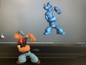
While CAD files store the comprehensive design parameters, STL files streamline the focus on physical form.
The bridge between them, forged through the reverse engineering process and 3D laser scanning, allows for a seamless transition.
Innovations in 3D laser scanning, artificial intelligence, and data processing algorithms promise to streamline the conversion process further.
These advancements aim to make reverse engineering more accessible, efficient, and capable of handling increasingly complex designs.